Here is the 3D-XplorMath menubar (when Surfaces is the currently selected Category):
Below we will discuss in turn each of the menus in the menubar, but first we wish to point out special features of two of the 3D-XplorMath menus. In reality, 3D-XplorMath is a collection of many closely related programs living under one roof. Each of the 3D-XplorMath Categories not only has its own collection of mathematical objects, but also needs its own special ways of visualizing these objects. For this reason two of the menus in the menubar are "context sensitive". As soon as the user selects a new Category, the third menu from the left (called the Main menu) changes to a menu with the name of that category. The Main menu is a menu of nouns---it contains the names of all the objects of that Category. Just to the right of the Main menu is a menu of verbs, called the Action menu. Generally speaking, a user first selects an object from the Main menu and then an action to perform on it from the Action menu. Since what you can do to an object depends on what Category it belongs to as well as its special characteristics, the Action menu is particularly context sensitive, and in fact it is re-created from scratch each time it is pulled down. The remaining menus are more stable. To continue the metaphor, they are menus of adjectives and adverbs; making a selection from one of them modifies the nature of the selected object chosen from the Main menu or of the action chosen from the Action menu. While these other menus change slightly with the context (e.g., certain items are enabled or disabled or change their names slightly) they are much more stable, than either the Main menu or the Action menu, and a representation of each is given below. Elsewhere we give a list of representations of the Main menu and a list of representations of the Action menu.
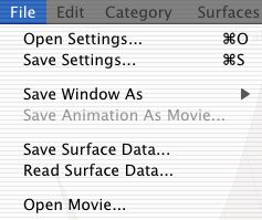
By tradition, the File menu has as its final entry the Quit command. It also contains, just above Quit, a Close Window command. This closes an active Dialog window, but not the main Graphics window, which is always open. The remainder of the File menu has the more interesting items for saving and restoring Settings files, saving the current contents of the Graphics mindow as a PICT file, saving filmstrip animations as QuickTime movies, and for exporting surfaces to Matlab and POVRAY, and importing surfaces from Matlab. Click here for more details on the File menu and just what its various items do.
Not used by 3D-XplorMath
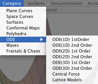
The Category menu simply lists the various categories of mathematical objects that 3D-XplorMath deals with. Choosing a particular Category makes it the "currently chosen Category", and makes its menu the current Main menu.
The Main menu is just to the right of the Edit menu and has the name of the current Category. It lists all the pre-programmed objects of the current Category, as well as any User Defined... items. In some cases, the current Category will have subcategories, and the Main menu will have submenus to reflect this fact. For example, the Surface menu has submenus that list non-orientable surfaces, pseudospherical surfaces, and minimal surfaces. A representation of the main menu associated to each Category is given with the documentation for that Category. Click one of the following category names to see the associated Main menus: Plane Curves, Space Curves, Surfaces, Conformal Maps, Polyhedra, ODE1D1stOrder, ODE1D2ndOrder, ODE2D1stOrder, ODE2D2ndOrder, ODE3D1stOrder, ODE3D2ndOrder, Central Forces, Lattice Models, Waves,Fractals&Chaos.
The Action menu like the Main menu is context-sensitive, and in fact it is created on the fly each time it is pulled down. Its contents reflect the current Category, and the currently selected object of that category. Click one of the following category names to see the associated Action menus: Plane Curves, Space Curves, Surfaces, Conformal Maps, Polyhedra, ODE1D1stOrder, ODE1D2ndOrder, ODE2D1stOrder, ODE2D2ndOrder, ODE3D1stOrder, ODE3D2ndOrder, Central Forces, Lattice Models, Waves.
3D-XplorMath has a large number of "parameters" and environmental variables whose values collectively determine how an object selected from the Main menu will be displayed. At the moment an object is selected, all the relevant variables are given carefully chosen default values that determine the default view of the object. A user never has to worry about choosing different values for these variables if he or she is content with this default view. However, for the more adventurous users, there is a simple and fairly uniform way of giving them new values. Namely, the various items of the Settings menu bring up different dialog boxes in which the user can type in new values to replace the current values. (Several other variables that act as switches are instead set using the View menu.) Below we give brief descriptions of some of the more important variables that are accessed from the Settings menu.
The integer "Scale" is just the number of screen pixels per unit of length. Suppose your screen resolution is 95 dots per inch and you set Scale to 95, If you are in the Plane Curve Category and select Circle from the menu, then the radius of the circle is the Parameter aa whose default value is 1, so the circle will have a radius of 1 inch. If you increase Scale to 190, the circle will be redrawn with a radius of two inches. (Similarly, if you leave Scale at 95, but set aa to 2 in the Set Parameters dialog, you will again get a circle of radius 2 inches.) The larger you set Scale, the larger details will look on the screen. However this will not show any extra detail unless you also increase the resolution parameters at the same time.
The Set Parameters dialog allows a user to set the values of nine parameters called aa,b,cc,...,ii. Most objects in the 3D-XplorMath galleries live in families that are described by one or more of these parameters. For example, as mentioned above, a circle has a radius which is given by aa, while an ellipse has two semi axis lengths, given by aa and bb.
[Note: The boxes in the Set Parameters dialog accept algebraic expressions, so you can enter 2 * pi instead of 6.283..., or sqrt(2) for 1.414..., or e for 2.71828.... Moreover, these expressions are evaluated in alphabetic order, so if you put 2*pi in the aa box and sqrt(aa) in the bb box, and e * bb in the cc box, then the parameter cc will get the value (2.71828...) * sqrt(6.283...). The expression evaluator understands all the standard functions such as exp, sin, abs, round, etc.]
The Set Morphing... dialog allows you to set the initial and final values of the nine parameters, aa, bb, ..., ii, used during a morph (and, for the surface category, the initial and final values of umin, umax, vmin, vmax). That is, during a morphing animation the initial and final frames are drawn using these initial and final values, and the values for the intermediate frames are determined by linear interpolation. Often it is convenient to set the initial and final values to the current values and then make a few modifications. To do this, click on the button "Init to Current Parameters".
The Number of Frames (N) in a filmstrip determines how an animation will play out, and can be chosen independently for the three types of filmstrips (morphing, oscillation, and rotation). For example, if you choose Rotate from the Animate Menu, the filmstrip created will consist of a full rotation of 360 degrees about the Rotation Axis, each frame being 360/N degrees rotated from the preceding. Making N large will give a smoother rotation that takes longer to play through the loop once. Choosing Oscillate from the Animate Menu will create a sequence of N frames, each rotated 5 degrees from the preceding one, and Playback will go through the loop and then back. This give a quick way of seeing a smooth rotation through a smaller range.
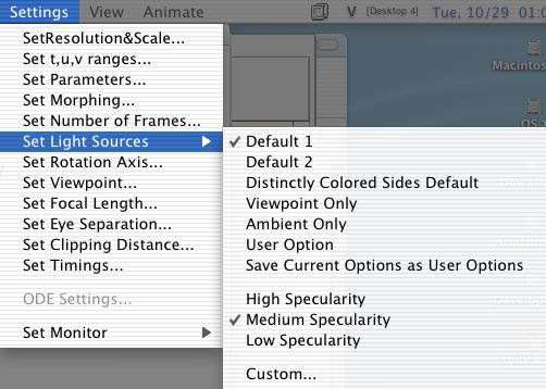
The Custom... item of the Set Light Sources submenu of the Settings menu brings up one of the more complex dialogs of the program. This lets the user set the color of the five light sources (Source0, Source1, Source2, Source3, and AmbientSource) and the direction of the light rays from Source1, Source2, Source3. The two parameters that determine the characteristics of specular reflection from a surface (Specular Exponent and Specular Ratio) are also set using this dialog. This dialog is used in combination with the Set Coloration submenu of the Surface menu to determine the color of a surface when the Color item of the View menu is chosen. See the section on color for more details.
Set Rotation Axis controls the axis about which an object rotates when one choses Rotate from the Animate menu.
Three dimensional objects in 3D-XplorMath are always centered at the origin, and they are "looked at" from a point in 3D space called Viewpoint. (The viewing camera actually looks at the origin.) Set Viewpoint allows you to set the value of Viewpoint manually, However it is usually easier to use the mouse to rotate the object into a good position. (This does not really rotate the object, but rather rotates Viewpoint in the opposite direction.)
Setting the Focal Length can be used to change the 3D-impression of objects viewed in perspective, Similarly, setting eye separation changes the amount of stereo separation when 3D objects are viwed in stereo mode.
There is an imaginary plane called the Clip Plane that is between the Viewpoint and the origin and perpendicular to the line joining them. Its distance from the Viewpoint is called the Clipping Distance and can be set using Set Clipping Distance. Any part of the object that is "behind" the Clip Plane (i.e., closer to Viewpoint) is invisible. This allows you to see inside a 3D object. To seehow this works, choose Pinkall's Flat Tori from the Surface menu, set Clipping Distance to 14, and use the mouse to start rotating the torus towards you, after putting CapsLock down.
Set Timings controls how fast the drawings are made and how fast animations proceed
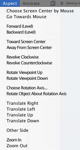
Before beginning a description of the Aspect menu it is important to understand a basic design feature of 3D-XplorMath: once an object is created in space, it is never moved or re-created in a different location. All different views of the object are created by using the well-known "alias vs. alibi" duality. For example, to make an object centered at the origin appear to rotate clockwise about the origin, we fix ImagePlaneCenter at the origin, and then rotate ViewPoint and ViewDirection counterclockwise about the origin, keeping FocalLength fixed. Similarly, to make an object appear to translate up,down, right, or left, we translate both ViewPoint and ImagePlaneCenter in the opposite direction, keeping ViewDirection and FocalLength fixed. Of course this only works because we are dealing with a single object at a time. If we had both a torus and an ellipsoid on the screen, and wanted to rotate one while we translated the other, the approach we are using fails. But since we are only dealing with a single object at any time, this approach both simplifies and speeds up the process of showing different views of an object.
Most of the pre-programmed three-dimensional objects in the program are symmetric with respect to the origin so it was natural to choose the origin as default ImagePlaneCenter. One of the early objects (Dini's Surface) seemed to look particularly nice when viewed from (10,-10,10), so that became the default ViewPoint, making the default FocalLength 10 sqrt(3), and default ViewDirection (-sqrt(3)/3, sqrt(3)/3, -\sqrt(3)/3). It is natural to choose Scale proportional to the linear size of the Graphics Window. After a little experimentation I chose one-tenth the sum of the height and width of the Graphics Window in pixels as the default value of Scale. (For a 420 pixel by 300 pixel sized Graphics Window, this makes Scale equal to 72, so a line segment of unit length on the ImagePlane will appear to be one inch long on a monitor with resolution of 72 dpi.) Finally, the default value of ClipRatio is one-quarter (giving a default ClipDistance of 4.33), and the default value of EyeSeparationRatio is 0.075 (giving EyeSeparation a default valure of 1.2). Of course, for certain objects, these default values are inappropriate, and the program changes them to other values before creating the default display of the object.
We next describe how to use the various items from the Aspect menu to change the aspect parameters in ways that will have desired visual effects. But remember that using virtual sphere mode will often be the quickest and most intuitive way to change the aspect parameters to desired values. The easiest to explain are the last two items, "Look at Origin From..." and "Choose Aspect Parameters...". The first of these allows the user to set a particular Viewpoint in space, after which the program adjusts other aspect parameters (FocalLength, ViewDirection, ...) appropriately. "Choose Aspect Parameters..." brings up a dialog that permits the user to set the parameters "by hand". Note that since ViewDirection is a direction, it is convenient to give it by its altitude (the angle it makes with the x,y-plane) and its azimuth (the angle its projection on the x,y-plane makes with the x-axis). You should not use this dialog to set ViewPoint unless you are sure of what you are doing and need some special effect---otherwiae, use "Look at Origin From..." instead. The reason is that using the "Choose Aspect Parameters..." dialog to set the ViewPoint will only change ViewPoint and not adjust the other parameters as they normally should be.
The others menu entries are more specialized and will be described in the order they occur.
(The Aspect menu is used in creating a Grand Tour, and is only visible then. . It is awkward to use and eventually will be replaced with a control panel having the same functionality.)
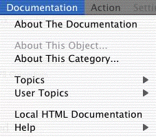
The Help submenu of the Documentation menu gives access to some of the same information contained in this documentation. The main difference is that it is not hyper-linked, and only basic items are covered.